BRAKING SYSTEM ESSENTIALS
*BRAKING SYSTEM ESSENTIALS*
NOTE: This is part 1 of a multi-post series; more to come!
Arguably brakes are the most important subsystem in your car;
nevertheless, they are mostly overlooked, either by not upgrading them when you
should or by throwing on a multi-piston caliper and calling it a day, without
it leading to an increase in braking performance (and sometimes even being a
downgrade compared to the stock setup). This motivated me to do a write-up,
explaining automotive braking systems in simple terms. Shall we?
Most vehicles on the market today are equipped with hydraulic disc
brakes, so this is the only type we will discuss. However, the same basic
principles apply to most braking systems. The fundamental function of a braking
system is to decelerate a vehicle by transforming kinetic energy to heat that
is subsequently dissipated in the environment. As such, braking systems are
characterized by two metrics; braking torque and heat rejection capacity. The
former determines how “strong” your brakes are; the latter determines for how
long they will be effective. This is a bit simplified, but we will dive deeper
in future installments when discussing brake pads.
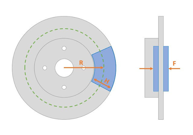
The mechanism through which a brake system generates braking torque is via sliding friction (through squeezing together the brake pads and the rotor) at an effective radius on the rotor that can be assumed equal with the location of the middle of the pad when viewed from the side. To make this whole thing simpler, let’s use a schematic.
As it is obvious at this point, braking torque depends on 2 factors; (i)
effective radius (R) and (ii) sliding friction.
Effective radius (denoted R in the schematic) is linked to the pad
height (H), which in turn is linked to pad area, and mostly with the rotor
diameter. As such, the larger the rotor is the more the braking torque applied
all else equal. In addition, increased rotor size means increased thermal
capacity and increased area that can be used for heat dissipation.
Unfortunately, it also means more unsprung mass and more rotational inertia,
which both hurt performance.
The second method to increase braking torque is by increasing the
sliding friction. Remembering high-school physics, one should recall that
sliding friction depends on two factors; (i) friction coefficient between the
surfaces in contact, (ii) normal force “squeezing” the surfaces together
(denoted F in the previous figure).
The sliding friction coefficient depends on the materials in contact.
Given that the rotor material is grey cast iron (except if you guys run fancy
carbon-ceramic brakes), the only system variable is the pad material. It is
worth mentioning that the coefficient of friction of a pad changes with
temperature, but this topic requires a future write-up on its own. Although it
may seem counterintuitive, the coefficient of sliding friction is independent
of the area of the surfaces in contact. However, potential surface deformation
of objects in contact does change the coefficient of friction; let’s keep that
in mind when discussing multi-piston calipers.
The final system variable is the normal force (F) exerted on the pads through the brake caliper piston(s). This is the (indirect) result of you applying the brake pedal. Several mechanical and hydraulic “levers” are used between your leg and the brake caliper, multiplying that force. These are as following:
- Brake pedal mechanical leverage (pedal ratio)
- Brake booster ratio
- Brake hydraulic leverage
The pedal ratio is the ratio of the distance between the pivot
(mounting) point and the pedal pad (X) to the distance between the pivot point
and the master cylinder (MC) actuation rod (Y). For simplicity sake we can
considered this fixed, as not many would change their brake pedal (it would be
hard to do anyhow, as the mounting point for the pedal and the MC is largely
fixed by design).
The booster ratio comes to play next. Effectively a booster is a
“pneumatic lever”; it uses vacuum through a diaphragm to increase the force you
exert through the brake pedal to the MC. Choices are quite limited here as well
(although certain parts interchange between NAs and NBs); for now, we can
consider this fixed as well.
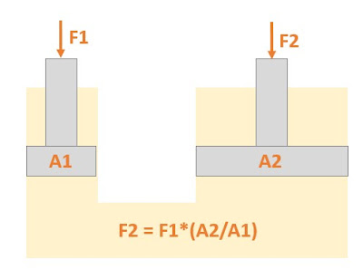
The last bit (and the most useful one to understand) is the hydraulic ratio or “leverage”. In order to grasp this, we will use a simple high-school physics example, where a single small piston (the MC) drives a single larger piston (the caliper). The input force (exerted to the master cylinder by the brake pedal) is multiplied by the ratio between the piston area of the slave to the master.
The reason this is important is that usually we want to maintain a
similar to OEM front-to-rear brake bias when upgrading our braking system (or
we want to shift that balance for a certain reason, but still in a predictable
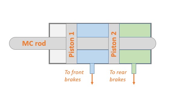
way). Typical automotive MCs are known as “tandem”, as they have 2 separate
pressure chambers, one in front of the other, using the same diameter.
Therefore, the front and rear brake circuit pressure is the same; any
difference in braking torque comes from the brake caliper total piston area,
effective pad radius and brake pad material.
As such we should pay attention when selecting these parameters; a
“stronger” brake in one end of the car is not necessarily a better braking
system. Too much of a rear brake bias will introduce unbalance, as the rear
wheels would lock up before the front ones. Too much front-bias and you are
not working your rear brakes hard enough, losing braking performance. As with
everything (automotive or not), balance is key. That being said, all of this braking torque needs to be transmitted through your tires, so your braking system at the end is as good as your tires too; upsizing everything to generate a ton of braking torque is going to result to an extremely sensitive system that is easy to lock up and does not allow for brake modulation. Pads, rotors and calipers are the biggest part of this equation, at
least for static brake balance. Dynamic brake balance is a bit of a different
animal and it would require revisiting basic physics again, so stay tuned!
(Also, if you have questions or a different view, feel free to initiate
discussion!)


Comments
Post a Comment